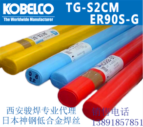
日本神钢KOBELCONO65G氩弧焊丝ER70S-2进口焊丝


- 面议
- 2024-11-19 07:30:02
- 日本
- 碳钢
- NO65G神钢焊丝,ER70S-2进口焊丝
- 陕西西安
- 郑经理 13891857851
- 西安骏焊焊材有限公司

- 新浪微博


- QQ空间


- 豆瓣网


- 百度新首页

信息介绍
详细参数
日本神钢KOBELCO NO65G氩弧焊丝ER70S-2进口焊丝
陕西西安骏焊进口日本神钢焊材
NO65G TIG rod, equivalent to AWS A5.18 ER70S-2, contains less C, Si and Mn contents than TG-S50 or TG-S51T; instead, Al, Ti and Zr are specially added. These elements help to decrease the amount of oxygen in the molten pool, allowing NO65G to provide a weld metal of relatively high cleanness. On the other hand, it is a little inferior to TG-S50 or TG-S51T in terms of fluidity of molten metal, because of which its surface tension increases while the oxygen content in the molten metal is decreased.
Because Al, Ti or Zr is an element with high oxygen affinity, slag can be generated on the bead surface after a part of the element combines with oxygen in the molten metal during welding. Users are therefore advised to beware of weld defects, such as poor bead appearance or slag inclusion, caused by the slag.
Each chemical element in NO65G rod is strictly controlled to maintain a narrow range within the AWS A5.18 ER70S-2 specification so that it can meet the tough requirements set out by Japanese clients for mechanical properties in critical structural projects.
Table 8: Typical chemistry of weld metal (mass%)西安骏焊
| C | Si | Mn | P | S | Cu | Al | Ti | Zr |
|---|---|---|---|---|---|---|---|---|
| 0.04 | 0.50 | 1.20 | 0.007 | 0.012 | 0.22 | 0.06 | 0.05 | 0.02 |
Table 9: Typical mechanical properties of weld metal
| Tensile test at RT | Absorbed energy (J) | |||||
|---|---|---|---|---|---|---|
| YS (MPa) | TS (MPa) | EI (%) | -40°C | -30°C | -20°C | |
| As-welded | 584 | 635 | 29 | Av 165 | Av 200 | Av 215 |
| 625°C × 8hr | 545 | 615 | 30 | Av 138 | Av 160 | Av 175 |
Table 8, Table 9 and Figure 5 show the typical chemistry of NO65G weld metal, the typical mechanical properties in as-welded and PWHT (625°C×8 hr) conditions and the absorbed energies in relat ion to the tes t temperatures, respectively.
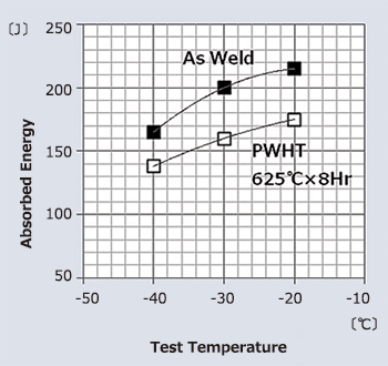
Figure 5: Impact properties of weld metal
Figures 6 and 7 show face side bead appearance after root and second passes and back bead appearance after root-pass welding in 1G and 3G (uphill) s by NO65G (2.4mm dia.), respectively. Figures 8 and 9 exhibit macro-structures of root-pass and second-pass welding in 1G and 3G (uphill) s, respectively. The groove configuration was of single 60°V, with a root gap of 3.0-3.5mm. The welding conditions were 110A-12V for root-pass without back-shielding and 160A-13V for second pass welding, respectively.

- NO65G神钢焊丝,ER70S-2进口焊丝
- 焊条
- 陕西西安
- 郑经理
- 日本
- 碳钢
- 是
- NO65G.ER70S-2
- 其它
- 其它
NO65G焊丝信息
-
 厂家直销科技展出租销售价格哪里最低面议
 -
 鲁兴优质12mm橡胶包塑链条护栏防护塑钢链条厂支持定做¥ 10
 -
 厂家优质外贸牛仔裤西藏林芝地摊库存欧美牛仔裤时尚杂款哈伦裤批发5元牛仔裤批发市场¥ 5
 -
 昆山环庆路管道检测供应商检测管道供应商¥ 100
 -
 C61900材质C61900化学成分¥ 56
 -
 丹东洒水车喷头改装改装基地¥ 88000