珠海UL认证中心,CUL认证实验室


- ¥2.00 ≥ 1件
- 2019-01-25 11:28:07
- 珠海UL认证流程,珠海UL认证费用,珠海UL认..
- 广东珠海
- 陶静 13913142465
- 深圳市优尔检测技术有限公司

- 新浪微博


- QQ空间


- 豆瓣网


- 百度新首页

信息介绍
详细参数
Wiring, Printed - Component
The devices covered under this category are incomplete in certain constructional features or restricted in performance capabilities and are intended for use as components of equipment submitted for investigation rather than for direct separate installation in the field. THE FINAL ACCEPTANCE OF THE COMPONENT IS DEPENDENT UPON ITS INSTALLATION AND USE IN EQUIPMENT SUBMITTED TO UL
GENERAL
The category covers printed wiring boards intended for use as components in devices or appliances. The boards may use organic or inorganic base materials in a single or multilayer, rigid or flexible form. Circuitry construction may include etched, die-stamped, precut, flush press, additive, and plated-conductor techniques. Printed-component parts may be used.
This category covers flexible printed wiring defined by the cross-sectional configuration, including right-angle conductors, mid-point connections, etc. This category does not cover flexible printed wiring where the cross-sectional configuration is the same for the entire length of the product. The latter construction is covered under Appliance Wiring Material (AVLV2).
The tests may include the determination of material flammability (burning characteristics), conductor adhesion, delamination, and silver migration. In addition, the effect of long-term exposure to elevated temperature (air-oven aging) on property retention may be investigated. Levels of performance characteristics required for a particular end-product application are intended to be in accordance with the requirements of the end-product standard. Due to space limitations, only a limited number of property values may be presented in the individual Recognitions. Additional properties may be found in the individual Reports.
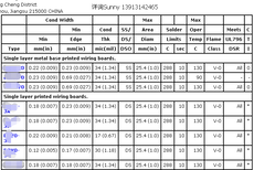
Minimum Cladding Conductor Width — The minimum width of any conductor spaced more than 0.4 mm from the edge of the printed wiring board.
Minimum Edge Cladding Conductor Width — The minimum width of any conductor parallel with and not spaced more than 0.4 mm from the edge of the printed wiring board.
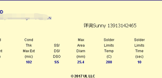
Cladding Conductor Thickness — The minimum metallic cladding thickness of the conductor. The cladding thickness represents the copper conductor thickness only, unless otherwise noted.
Number of Clad Sides — Indicates whether the printed wiring boards have a pattern on one side (denoted as single sided [SS]) or on both sides (denoted as double sided [DS]).
Maximum Area Diameter — The maximum unpierced conductor area of a printed wiring board is judged by the diameter of the largest circle that can be inscribed within the pattern.
Solder Limits — Unless designed for hand-soldering only, each printed wiring board construction is assigned a maximum temperature and dwell time. The tabulated levels are the maximum temperature and cumulative time conditions to which the boards may be subjected during assembly of components. Multiple solder limits are used to represent surface-mount technology (SMT) soldering process maximum temperature and time profiles.
Maximum Operating Temperature — The maximum continuous-use temperature to which the printed wiring board may be exposed under normal operating conditions in the end product .
Flammability Classification — Processed printed wiring boards with or without applied coatings, finishes, etc., as supplied to the device or appliance manufacturer, may be classified based on burning tests conducted in accordance with ANSI/UL 94, "Tests for Flammability of Plastic Materials for Parts in Devices and Appliances," at the option of the manufacturer.
Where such testing has been conducted, the printed wiring board is classified as HB, V-0, V-1, V-2, VTM-0, VTM-1 and/or VTM-2 .
Conductor Finishes — Metallic plating on conductors, contact fingers, plated thru-holes, etc., may be tested at the option of the manufacturer.
Direct Support of Current-carrying Parts — A printed wiring board that meets the minimum ANSI/UL 796, "Printed-Wiring Boards," levels of direct support of current-carrying parts is identified to enable the OEM to select appropriate printed wiring boards for use in products. Direct support is not investigated for "Flammability Only" boards and should be considered during the end-product investigation.
The required performance levels are shown below:
(一) FR-4,FR-4.1,FR-5单面板及双面板认证申请
(二) cem-1,cem-3单面板及双面板申请
(三) FR-1,FR-3单面板及双面板申请
(四) FR-4多层板申请
(五) 单面铝基板仅燃烧认证和全认证申请
(六) 双面铝基板仅燃烧认证和全认证申请
(七) 多层铝基板仅燃烧认证和全认证申请
(八) 铜基板 单面,双面,多层 仅燃烧认证和全认证申请
(九) 柔性线路板(软板)仅燃烧认证和全认证申请
(十) 软硬结合板仅燃烧认证和全认证申请
(十一) 线路板基材认证申请
(十二) 线路板油墨认证申请
(十三) 覆盖膜,电磁膜,屏蔽膜认证申请
(十四) 已有UL,增加CUL认证申请
(十五) 其他认证申请
(十六) XPC板材 22f板材 HB板材 V0板材
详询Sunny 陶 1822971259
- 珠海UL认证流程,珠海UL认证费用,珠海UL认..
- 电子行业认证
- 广东珠海
- 陶静
珠海铝基板UL认证信息
-
 臂板蛋白3FS3FELISA试剂盒(酶免分析法)说明书¥ 1
 -
 水库专用启闭机厂家供应四川江安螺杆启闭机5吨启闭机面议
 -
 精密不锈钢铜铝件孔内死角去毛刺抛光设备¥ 34000
 -
 优质C3604黄铜管规格C3604铜排硬度¥ 45
 -
 前四后八挖机拖车¥ 100000
 -
 天津进口钻井设备报关代理面议